Royal Enfield Interceptor - Knowledge Base
The Notorious Interceptor Cyl. Head Oil Pressure Problem
A long chronicle of E-mails
| Unless stated otherwise, the information in this Knowledge Base is for Royal Enfield Interceptor only. Some information could of course be applicable to other models. |
Index
A
fundamental problem in the S II 's Lubrication System (Ole)
Oil
Pressure Problem (Bill) (see Bill's Interceptor)
TECH
NOTICE. (Quaser)
More
on the search for better oil pressure (Bill)
Thoughts
on Pulsation Dampener (Bill)
Oil
Pressure No Better (Bill)
Important
notes from manual (Kickan)
Notes
on the Windkettle (Bill. Ole)
A
little more windkettle news (Bill, Ole)
Rolling
Lab - Oil Pressure Improvement (Bill, Ole)
Pump
cavitation has to be the culprit (Ole)
Thoughts
on Oil Pressure, cavitation, etc (gREgg)
Alarmingly
little oil drips off the exhaust rocker arm (R. Fisher)
There
are 3 leak passages in the pump : (Ole, Bill)
I
used a chamber capacity around 20cc (Peter - is Back)
A
picture that shows how the trick is done
Trochoidal
- Pump (gREgg)
Driving
the pump by means of a spade connection(gREgg)
A better Norton Oil Seal for Timing Cover/MainShaft Seal(Ole)
Tips for better oil flow and thoughts on Oil Pump (gREgg)
Quick two start driven oil pump(Bill, gREgg)
External oil pump off the tachometer drive (Tom)
Modified Pump Ports (Ole)
Electric Oil Pump! an Interceptor Pacemaker(Paulus)
Actual specs of the Tacho driven pump(Tom)
Electrical Oil pump for a test(Tom)
Search for better oil pressure - Oil Pressure Update(Bill)
Thicker Oil Helps too!(Bill)
Using a Honda Oil pump (with drawings)(Ole)
There are 3 leak passages in the pump :
Bill, ( may I call you that instead of Madmax ? )
You seem to worry a lot about the leak-rate internally in the pump and you might be right in doing so !?
There are 3 leak passages in the pump :1) The face between the Rocker Body and the Timing Cover. Greg mentions this issue in his latest mail. Sometime back in the 80's I noticed some minor marks - as would come from trapped particles - on the face of my Rocker Body. It was ground smooth again and reseated with fine grinding paste. Still looks good today. There is no harm done in taking off material from that face. It only means that the plunger will ride further inwards on the pump-crank.
As for the spring load ( which of course will decrease a little with the above fix ) - my set-up has always "seemed" adequately high !?
Since I have lowered the primary, 60 psi, relief valve setting to 45 psi , I'm not so worried about that spring.2) Plunger / Rocker Body bore. Seems to me there is a good fit here and no measurable wear. The choice of materials must be pretty good !
3) Past the Pump-Spindle. This is probably the biggest leak-path. But since it is only relevant on every second pump-stroke ( when the Plunger moves out of the Rocker Body ) I don't think you should worry too much about it. On my parts, at least. the radial gap is not alarming. There is a tricky question here though : Is there a facial seal between the Spindle-flange and the casing ?.
The Wormdrive-force on the Pump-Spindle is in rearwards direction - opening up that facial gap , whereas the pressure in the pump will try to push the Spindle forwards ! I'm pretty sure that 60 psi ( and also 45 psi ) on that diameter will exceed the Wormdrive-force ! So whenever the housing is pressurised, the Spindle will be pushed forwards and the facial seal will help keep the pressure in there. On every other stroke - when there is suction in the Pump housing - the Spindle will definitely move rearwards !
So, if there is too much axial play in the Pump-Spindle, you will loose pump-efficiency - corresponding to the volume created by the reciprocating Spindle !! A good way of getting that axial gap right is probably to keep the assembly in a 100 degr. C oven for som time and then check that the gap is big enough for an oil-film - ( well, actually two ) and no bigger !
Finally, of course, there can be a "valving leak-path" if one has been messing with the ports and hasn't been very careful.
( I have made a series of drwgs of the original - and a modified valving pattern - if you are interested. - Can you reed .dwg files ? or .jpg - ? )
Building on a gearpump - for total substitution - is my highest priority at the moment. Before I get to the point of designing adapter parts, however, it is necessary to find a suitable pump ( with capacity of approx. 2 cc pr pump rev. ! - if anybody would like to help !? ) and then conduct an experiment to assure that the pump can handle the suction-height !??? Normally, it is said that gearpumps can't get started if there is any suction height at all ! ( non self-priming ). But I have a Gilera Saturno, with a gearpump ( unfortunately too "thin" and big-diametred for the RE ) that works brilliantly with a suction height of approx 1,5" ( 40 mm) !Picture yourself, after start, staring intently at an oilpressure-lamp - and after a little while - having to tilt the whole bike violently down on the right side in order to get the pump started and the warning light to turn off !?
Best regards
OleOle,
You can call me Bill if you like. When I signed up I thought everyone used a handle but I can see now that that isn't true.
The reason I am worring about the internal leak rate of the pump is that there is a big difference between the theoretical flow rate and the actual flow rate (with hot oil). I found a formula for calculating the pressure required to push oil through a hose at a given flow rate. This formula showed that the pressure is directly proportional to the viscosity. Then I found a graph that shows the viscosity as a funtion of temperature.
For SAE 50 oil, the viscosity at 215F is about 100ssu. At 300F, the viscosity is down to 47ssu. This indicates that lowering the temperature of the oil will improve the oil pressure (which I think everyone would agree with) but it also indicates that it would take nearly a 100 degree drop to double the pressure. This, I think, is not going to happen even with two oil coolers.
My experiment with water pressure indicated that the worst leakage is the seal of the rocker body to the timing cover. Next time I take the cover off, I am going to lap this surface very carefully to see if there is any improvement.
I also thought there could be a lot of leakage down the pump spindle but I think it is not too bad. There is no seal of any kind on the pump spindle. I agree that 45 psi in the pump housing will move the spindle into the housing against gear force but I don't think this will make much difference. Your comment regarding the lack of wear in the pump housing and spindle is something I have also observed.
I think this indicates that there is plenty of leakage in these areas and therefore everything is riding on a film of oil so there is no wear!
I really like the gear pump idea. In my professional life, I have used gear pumps on crane hydraulic systems and I have seen them lift the oil more than 2 ft. during start up. I don't think the gear pump will have any problem with suction. I would really like to see your drawings. I can read .dwg and .jpg files without any problem. I use AutoCADD everyday so send me whatever you have.
Thanks a lot for your comments. It's great to have someone to discuss this issue with.
Best Regards,
Bill (Madmax without the disguise)I am watching this discussion with great interest. Don't know if your aware but Triumph Tridents / BSA Rocket threes used a gear type oil pump and these units really put out but may be physically to large. In my humble opinion I would recommend staying away from plunger type pumps as fitted to Triumph and BSA twins (as someone suggested). When BSA / Triumph designed the Triple they sought to address the twins shortcomings and the oiling system was one of them, hence the fundamental change in pump type.
Keep up the good work.
Rick Fisher
(Peter is Back) Hoi, You found me again.Its a while back since I sent that oil letter. When was that ? Never found the site again. But then I hardly ever surf.
I used a chamber capacity around 20cc. It cured the problem even at 35 C hot France using cheap 20/50 oil. No mods to the oilways. To get a significant amount of oil to the heads we diverted the flow from the pressure relief valve to the heads in stead of straight to the tank. Oil being subject to gravity we trusted it to get down there anyway. I'll reread the other letters carefully and get in touch again. best regards Peter
Hi Royal,
You're looking for the evasive Peter.. well, I hope to meet him one of these days and will inform him. Or you can try to reach him via the dutch Enfield club.. he's very active there.
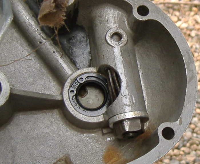
In the meantime I can send you a picture that shows how the trick is done.See attachment..Cut a piece of aluminiumsheet and make it fit on the inside of the timingside cover. Before you weld this to make a chamber of about 10cc you have to drill the hole downwards just into the oil feed to the pump. Exactly in the 90 degree angle where the oil feed diameter goes from 4.8 mm to 3.5.
Kind regards
keep up the good work!
Paulus B
Trochoidal - Pump.
1. The correct spelling for the type of pump under discussion is:
'Trochoidal'. The following site has a very good overview of the design:http://fluid.power.net/techbriefs/papers/proc_gamez_montero.pdf
2. Trochoidal pumps are very common in Japanese bikes, but the down side is that, like all trochoidal pumps they are fairly large.very easy to remove.
3. As an example, the pump on a Honda CB 400/500/550/650F is fastened to the left hand crankcase, and runs off a slot cut into the end of the primary drive idler shaft. Some of the later Honda twins also had trochoidal pumps which were chain driven. (Do not confuse these with the early pumps that were a plunger pump running off an eccentric on the clutch center).
4. Seems to me also, that the VF500F (Vee-four) oil pump was chain driven as well. A nice feature is that these pumps generally have pressure relief valves built in.
Not sure that teh timing side of an Enfield twin engine has enough room to hide such a large pump, but it's a start.
.. gREgg
Ole and Bill,I've taken the liberty of copying Royal with this message, so that he can amass the information for eventual publication in the web site.
The mounting on the timing cover as mentioned below makes a lot of sense, as well as teh method of interfacing to the pump ports. Many of the ideas are similar to the ones I've been toying with, especially the notion of driving the pump by means of a spade connection, which is essentially self-aligning. Various engines use this for oil pump drives, as well as in the tach drive.
We should be careful to enlarge teh holes in the timing cover to ensure enough flow, as well as throughout the engine. The other related item, as surmised about 25 years ago by the late Jack Gray, is that some of the internal passages of the engine may not be large enough. It is for this reason that I reviewed, enlarged, radiused and smoothed all the oil passages in my engine when I rebuilt it. BTW, in place of O rings, I tend to use Quad Rings, which are much the same, but have a near square cross section, and thus seal much better. They are commonly used in hydraulic systems, and I use one in a mod I do on the earlier twins to eliminate an oil leak between teh cylinders where the rocker feed passes from one side of the cases to the other.
The round oil pump Bill saw in the magazine is most likely the stock pump from teh BSA B31/33/Gold Star engine family. I ran roller bearings everywhere, so I don't imagine it has teh capacity nor the pressure for the job at hand. (I have a Gold Star DBD34 engine here, however if any details are required). The stock pump is made from a particularly cheesy cast zinc material, and I have seen several of these pumps badly cracked, likely from water freezing inside them.
Something I should point out is that my twin is a Series 1A, which means I have the additional issue of a return pump. Good idea about marketing the pump to the India Enfield crowd, but keep in mind those engines are dry sump as well, meaning they'll need a return pump too. All this said, I have not actually put a pressure gauge on my dry sump oil system to see if I have a problem, but as you likely know, the oil feed to the heads on the early engines do not rely on the big end relief valve blowing off.
I should mention a theory of mine, relating to the rocker feed oil lines. I've replaced mine with the early "Y" style pipe from the 700cc engines. This is based on information I've read that came to light during the early development of the Bullet engine. The first couple of years, the Bullet had a 'T' shaped pipe, similar to the concept of the late Inter, but fed from
the center. They quickly replaced teh 'T' pipe with a 'Y' pipe, because it turned out that at speed, most of the oil was flowing to the inlet rocker. The 'Y' junction split the feed more equally. At any rate, the change was simple, and the 'Y' pipes are a cleaner layout.
Something else that's crossed my mind from time to time is that Matchless/AJS had a similar pump drive shaft to the Interceptor, but purposely cut a spiral groove in it where the locating dowel fit in it. This made teh pump shaft reciprocate end-wise, and formed a pump action.
Lots of capacity, because the shaft was at least 12.7 mm in diameter... gREgg
A better Norton Oil Seal for Timing Cover/MainShaft Seal
My engine is a later type and has the tapered valve body - but it still blew out the original feed seel that was then turned into minced metal and rubber by the worm-drive. If anybody is interrested I have drawings of a mod. replacing the seel with a Commando seal( slightly lower - leaving space to put in a groove for a lockring !).
Ole
In an extensive rebuild, Kickan, took this to heart. Thanks Ole for the detailed instructions and part no's which Kickan too to the engineer that enabled this circlip with the Norton Seal to be used.. See picture with click for larger pic.
Tips for better oil flow and thoughts on Oil Pump (gREgg)
I've taken the liberty of copying Royal with this message, so that he can amass the information for eventual publication in the web site.
The mounting on the timing cover as mentioned below makes a lot of sense, as well as the method of interfacing to the pump ports. Many of the ideas are similar to the ones I've been toying with, especially the notion of driving the pump by means of a spade connection, which is essentially self-aligning. Various engines use this for oil pump drives, as well as in the tach drive.
We should be careful to enlarge the holes in the timing cover to ensure enough flow, as well as throughout the engine. The other related item, as surmised about 25 years ago by the late Jack Gray, is that some of the internal passages of the engine may not be large enough. It is for this
reason that I reviewed, enlarged, radiused and smoothed all the oil passages in my engine when I rebuilt it. BTW, in place of O rings, I tend to use Quad Rings, which are much the same, but have a near square cross section, and thus seal much better. They are commonly used in hydraulic systems, and I use one in a mod I do on the earlier twins to eliminate an oil leak
between the cylinders where the rocker feed passes from one side of the cases to the other.The round oil pump Bill saw in the magazine is most likely the stock pump from the BSA B31/33/Gold Star engine family. I ran roller bearings everywhere, so I don't imagine it has the capacity nor the pressure for the job at hand. (I have a Gold Star DBD34 engine here, however if any details are required). The stock pump is made from a particularly cheesy cast zinc
material, and I have seen several of these pumps badly cracked, likely from water freezing inside them.Something I should point out is that my twin is a Series 1A, which means I have the additional issue of a return pump. Good idea about marketing the pump to the India Enfield crowd, but keep in mind those engines are dry sump as well, meaning they'll need a return pump too. All this said, I have not actually put a pressure gauge on my dry sump oil system to see if I have a problem, but as you likely know, the oil feed to the heads on the early engines do not rely on the big end relief valve blowing off.
I should mention a theory of mine, relating to the rocker feed oil lines. I've replaced mine with the early "Y" style pipe from the 700cc engines. This is based on information I've read that came to light during the early development of the Bullet engine. The first couple of years, the Bullet had a 'T' shaped pipe, similar to the concept of the late Inter, but fed from the center. They quickly replaced the 'T' pipe with a 'Y' pipe, because it turned out that at speed, most of the oil was flowing to the inlet rocker. The 'Y' junction split the feed more equally. At any rate, the change was simple, and the 'Y' pipes are a cleaner layout.
Something else that's crossed my mind from time to time is that Matchless/AJS had a similar pump drive shaft to the Interceptor, but purposely cut a spiral groove in it where the locating dowel fit in it. This made the pump shaft reciprocate end-wise, and formed a pump action.
Lots of capacity, because the shaft was at least 12.7 mm in diameter... gREgg
Quick two start driven oil pump(Bill, gREgg)
In message no. 77, Peter in the Netherlands refers to the "quick two start driven oil pump". Does anyone know what this is? Is there a drive shaft/gear option that drives the pump twice as fast? Is he refering to a difference in the pump drive between a Series I and a Series II engine?
BIll
I missed the original message, but this was a trick adopted by numerous Brit
manufacturers.There is a so-called "two start" pump worm, which drives the spindle twice
as fast as the older single start worm gear. The spindle is the same in
both cases. I'm not certain when it was introduced, but it certainly
appeared in the Series 1.
.. gREgg
External oil pump off the tachometer drive (Tom)
Hello I am the guy that was 14&1/2 that put a knobby tyre on my RE and road it in the dirt. (Yes Tom , we enjoyed that off the Users Stories!/ Royal)
I have been reading all about the oil system problems on the Interceptors. I have a lot of info you my want. I had a 64 Interceptor and found that the oil just plane got way to hot! I live in California and it can get over 100F in the summer. Now get stuck in LA traffic on a freeway with no airflow over the engine, HOT! Try driving back and forth on a dry lake bed full throttle till somthing blowes up Real Hot! Or just cruse at a sustained speed of 65MPH or above for say around 500 miles with in 100F + Temps.I rebuilt my engine three times in 11 years. In the end I built an external oil pump (gear type)driven off the tachometer drive. The goal for me was to keep the heat from killing the oil. The hottest spots in the engine are around the exhaust valve guides. The oil in my engine burned there, leaving carbon deposits. The Interceptor runs great when the engine is cold. Smooth and quiet.
When the engine heat kills the oil it clatters. I tried a heat treated oil called Thermo-Vac. It made a big change for the better. I used that oil for 6 months. I then changed back to castrol GTX and all my problems came back.
I couldn't find the Thero-Vac oil anymore. I built an oil system that took oil from the oil tank through the pump to pressure relife valves to a spin on oil filter for a small car to an oil
cooler from a corvair then back to the oil tank. I never tried to feed the oil to the stock system to boost the oil pressure because the 64 is a dry sump and the return pump would not handle the extra flow. So did it work?Yes! It worked great! Keeping the oil cool keeps the pressure up. The stageII because of the wetsump could take pressure feed oil from this system and would work even better. The film strength of oil prevents metal to metal contact but volume of oil flow is needed to remove the heat build up. The action on the pump on a cold engine would open the relief valve that was set at 30psi. When the engine was hot the relief valve would not ! open till around 4000 RPM. The return line from the cooler had a good steady flow on a hot engine and a little less on a cold
engine.The volume of the pump that I made was arrived at using the guess and bygolly method and by a fluke it was right on. If this is posted and any of this Info is of any use to anyone and you need
more details. Just send a responce to me on this site www.ozemate.com/interceptor/hello.htm. I will drop in from time to time to check.
Tom
Modified Pump Ports.
Bill,
Promised you the drawings I made some time back of modified pump ports.
( The .dgn file is the original -but it seems to have translated ok to .dwg ?
I also have bitmap files of these drawings if anyone is interested - but they are really heavy !If we find a solution with a gear pump ( or a trochodiodal (sp) pump ? - as Rick suggests ) all these modifications with windkettles and valving port modifications will be history !
Ole
Paulus
Re. Copyright, where possible I'll try contacting authors etc.
Just send it to me when you get a chance,
Re, "Pacemaker" (below)
sounds Great, Go for it, and keep us posted.
REgards
Royal
Hi Royal
I'll scan some articles.. You have no worries about copyrights.. or shall I keep to the older stuff..?
In the meantime something else..
I read about this idea to put an additional oil pump on the tacho drive to bring cool oil to the head. I have been playing with the same idea, but with a small electrical ump. I orderded this pump from a medical supply firm. It is meant to bring life saving fluids in the body of sick persons.... and that should fit its use on a Interceptor for hot days I think.. It pumps with low pressure about 5 ltrs an hour and uses 7 watt / 12 volt. (You can go for smaller versions of this pump .. using only 3 watt.) They assured me it can handle hot fluids like engine oil. The system is extremely simple.. a rotating arm 'massages' an flexible (silicon) pipe and pushes the oil forward. It it self priming and has no problem with running dry.
The good thing with an electrical pump is that you can put it in every place and in every position you like, under the saddle for example. And with a switch you can put it on only when you need it.
I am installing the thing on my interceptor for a test.. For a start I intend taking the oil from the sump by a pipe through the fill-up opening. From there through the pump to the heads. (I dont know if this is original, but in on my Interceptor there is a nipple in the middle of the heads.. I suppose it was meant for a breather pipe..)
For whoever is interested.. for information about this pump you can look athttp://www.asf-thomas.de/liquid and look under 'schlauchpumpen'.Well its all in german, but they sure must have an english version too..
kind regards
PaulusActual specs of the Tacho driven pump
I am going to try to get the actual specs on the pump. It may take some time and may not even be possible. This bike was sold 24 years ago to a friend. The last time I saw him the bike was buried in his garage and I couldn't even see it. He may have even sold it. I have called him and get his answering machine he has called me and gets mine. He is 692 miles away so I can't just drop in.
What I can do is tell you what I recall. First off I knew that what I was going to build would be using used but serviceable parts. I worked for an aircraft rebuilding station. The gears were from an aircraft engine. I am not sure what engine just that it was a Pratt and Whitney or Curtis Wright 3350, 2800 or R2000 air-cooled piston driven radial engine.
The numbers are cubic inch displacement. The pumps in these engines are stacked, multiple gears that slide on a set of shafts, one that is keyed ( the drive shaft ) and one that is smooth ( the idler shaft ). The same gears are found in some automotive pumps. One gear on an idler shaft the other is usually one piece gear and drive shaft do not separate.
Now what I did was to cut down the length of the pump gears to around .500 to .750 inches long, this is just a guess. The idea was to make a pump housing that if need be could be shortened along with the gears to reduce the volume of flow.
I knew that the pump would not be perfect and would have some internal leakage. For this reason I built it for error on the side of OVERKILL! The relief valve is just an inline check valve with a 30 psi spring.
My housing for the pump has a seal at the drive end to prevent any oil from leaking into the crankcase and turning my dry sump into a wet one. It also has a small hole that feeds pressurized oil just behind the seal to lube the driving shaft of the pump. The housing is round and can be chucked up in a lathe and turned down. It has an integral boss that fits into the timing case tach drive mount. The mounting screws are recessed inside the pump housing. The cover is round and matches the pump housing, about 3/8 inches thick.
The pump looks good. The oil lines leave a lot to be desired, just plain black oil line. I am not sure but I think that I used 3/8 inch lines. The suction line is taped into the tank to take oil from the top portion of oil. It should be the hotter oil since the return line of the engines oil pump is in the filler neck and heat rises. This also is at a point that if the system failed and the oil pumped to the ground and not back to the tank it would leave plenty of oil for the engine.
The return line and the bypass line tap into the filler neck on each side just opposite each other so that they could be monitored. The oil filter is inside the tool compartment and can't be seen. The oil cooler is behind the passenger peg on the right side. It gets good airflow when the bike is moving and doesn't need it when it's not.
I think that the cooler looks good. It's from a covair and all aluminum. It has a one bolt mount and after shaving all unnecessary metal off polished up good. I intended to replace all the oil lines with stainless braded lines to get a better look but sold it before I did. If I can I am going to buy the bike back. I have yet to fully test this system on a hard ride but was quite surprised at and pleased with the initial results.
I should mention that I am a machinist and I own my own shop now. At the time I built the pump I had access to a full machine shop. The flow is as much as the oil cooler and filter can take at 30psi with hot oil. The pump speed is half the engine speed and is driven with a spade drive off the cam. It replaces the tach drive. In priming the pump the output line was held over a bucket. I revved the engine a bit, it primed and as I recall it hit the wall.
I would guess that the pump could empty the tank in less than 60 seconds. This system just cools and filters the oil. Tank to pump to oil filter to cooler back to the tank. The relief valve is tee-ed just after the pump back to the tank. Think about it when you just start your bike and it is still cool but not hot.
How does it run? Now what would it be like if it ran that way all the time. For me that is the only time the engine oil pump worked right. The engine oil pump is way to small to move enough oil through a cooler to do any good. In fact I would think that the extra resistance of an oil cool would tend to increase internal leakage of the pump, reduce flow and any gain in retaining oil viscosity would be lost in volume output. Resulting in little or no gain in oil pressure to the engine. It would be like trying to put out a campfire with a squirt gun. That is after all how the pump is built, like a squirt gun.
If nothing else this information should give you all more to ponder. I think that's about it for now till I get more Information.
Tom
Electrical Oil pump for a test
Hi Royal,I installed this electrical oil pump for a test.. had it running for some 5 hours and I have the impression it works as expected. Its a delight to see the oil cascading down the head when you look through the tappet inspection opening.
The current it draws is really low.. 7 watt, can run for many hours without exhausting the battery. Only question is.. as Dave remarked .. what is the life expectancy of the tube inside the pump? I was advised to use a neoprene quality, as it is stronger than the usual silicone.
Now, should this tube start leaking nothing serious happens.. it stops pumping and only some cc of oil will run out. And it works with a click-on system for replacing these tubes.. But of course I hope it will stay together for a long time...
As it is I mounted it besides the battery for testing. When no problems occur I'll move it to a place under the sadlle.. I made a bracket for a try out and found out there is space enough.
Send you two pics to give an impression. When the salt is from the roads Ill give it a serious test...
I'll make a new scan for those articles.. higher resolution.. smaller size..
Regards, Paulus
This is really a clever modification. I hope we can find out what kind of improvement this makes and how long the tubing lasts with the hot engine oil running through it.
MadMax
I got curious about electric oil pump alternatives and looked around on the web and found a site that has small 12-volt positive dispacement pumps. Would something like the model at www.greylor.com/catalog work? Gear pumps can be very reliable; I
still have fears of tubing failure in parastaltic pumps.
Dave
Search for better oil pressure - Oil Pressure Update
I built a pulsation dampener into the timing cover just as shown in this link. It did make an improvement but not as much as I would have liked. With SAE 50 weight oil and standard relief valves, I saw a maximum of 75 psi on start-up (70 degree F outside temperature). This quickly dropped to 60 psi after about 1 minute. The test run was about 2 miles at 40 mph then 10 miles as 70 mph. Halfway through the 10 mile section, the oil pressure stabilized at about 20 psi, more than twice the pressure I have been seeing. The engine seemed to run much better with the higher oil pressure. Next test will be a reworked seconday relief valve with the pressure raised from the current 20 psi to about 40 or 50 psi.
Bill
Thicker Oil Helps too!Some time ago we had a discussion about oil pressure, but as far as i remember we never included the oil used. As this was a very hot summer over here with plus 30 celsius temperatures the 20/50 oil in my interceptor II got very thin and oil pressure worried me.
I have a warning light that is on when pressure drops below 10 psi. With a cold start all was fine, after 10 minutes it lights up when idling, after 30 min. on the highway the light was on below 2500 rpm and above 3500 again.
(my theory is that at low rpm the pump just doesnt give enough pressure, but at speed the centrifugal force throws the oil faster out of the (worn) bigends than the pump can deliver ????) Still.. the temperature on the oil in the cranckcase hardly ever gets above 85 degrees celcius..
Anyhow.. before spending money on new big ends I tried a somewhat thicker oil (Penrite 25/60) and see.. oil pressure is back all the time! Can it be this simple?
Paulus
Using a Honda Oil pump (with drawings)Dear Royal
Hope you have recovered more or less fully by now !?
Since spring (in Denmark) when Bill (Madmax) and I had lengthy discussions about a replacement pump for the ol' SII - and Bill helped me buy Honda pump-parts ( through BikeBandit ) at astonishing low prices - things have been quite busy here and it is not until now that I have been able to finish the proposal for a replacement pump.
You will find drawings enclosed that should give a pretty clear picture of what the proposal looks like and how it works.(click for large picture)
A few technical remarks about the pump :
- Larger flow ( 3,4 cc against optimistic 1,8 cc originally ) does not mean larger velocity in the suction line since the Gerotor-type pump deliveres ( and sucks) an almost continuous flow as opposed to the original with its sinus-type pulsation.
- With the position of suction- and pressure ports well above the pump cavity the otherwise well-known phenomenon of draining of the pump during long stand-stills should not occur.
- All pressure in the pump ( and the suction line ) is sealed-off externally by means of O-Rings. So this pump will be oil-tight ! Only possible leak-path for the pressure is along the shaft and into the Timing Chest. As the old pump-housing is now a pressureless coupling-housing with connection to the Timing Chest, a fluid-gasket between the new Pump Adapter ( item 2 ) and the original Pump-Cover face of the Timing Chest should be ok.
- The Port Adapter Block ( item 1 ) will be produced in slight over-length. Its length shall be individually adapted to the depth in each owners pump-housing - so that when inserted without O-rings it is flush with the Pump Cover face.
In order to use this pump and benefit from its larger ( and stable !) flow some further modifications are necessary :
1) The crankshaft Feed-seal in the Timing Chest must be secured.
2) Flow-paths through the rocker-lubrication system must be increased by grinding additional "grooves" in the rocker-shafts - and/or otherwise. This will greatly improve cooling of the Tops as well as the camshaft pockets in the top of the crankcase. Idea is to move heat - via the oil - down to the lower part of the crankcase which - as we know - is formed as a large finned reservoir. As all SII owners have probably witnessed, every thing else than that bottom part of the crankcase becomes extremely warm if you do a bit of hard riding - and that's because the oil - with the original pump - hardly participates in the heat exchange process !
3) The Pump Spindle needs to be modified ( see later ).
Now to the action point : Will you, Royal, help me find out if any of the other SII owners are prepared to go ahead with this project ? As can be seen from the drawings, it requires CNC-machining of 4 parts plus some modification work. My guess is that the pump can be produced for approx 300 US $ if the quantity is 5 - 10. If anybody has a Chinese connection I will be happy to deliver IGES-files and drawings and then we might be able to build it cheaper ? ( The cost of the standard parts, including the Honda parts, is practically neglible !) I want to emphasize that I have no commercial plans with this project, I just want that pump, and if anybody else feels the same way it will be cheaper to build.
Last point is the modification of the Pump Spindle. I see 3 alternatives :
a) Leave as original and make a coupling that is driven by the crank. ( Bill(Madmax) option )
b) Braze on a coupling-disc that fits over the crank and has a slot perpendicular to the crank-line.
c) Grind off the crank and spark-machine a slot in the middle of the disc - leaving the original disc-face rim unbroken to act (as before) as axial bearing.
Hope you didn't choke in all this
Best REgards
Ole


kboil2a.htm