Royal Enfield Interceptor - Knowledge Base
The Interceptor Engine
Notes and Modifications
| Unless stated otherwise, the information in this Knowledge Base is for Royal Enfield Interceptor only. Some information could of course be applicable to other models. |
Index
General Engine Modifications
Primary-Belt Drive
Clutch Adjustment Advice
Clutch Re-Build Information
Bonding the cork segments Advice
Clutch and Gearbox Assembly notes
Gearbox Neutral Finder notes
Cut the clutch rod in 2-3 places!
Torque Values Advice
Numbers-Engine-Frame Advice
Notorious Oil pressure Problem for Cylinder Head
Enginge Breathing tips
Failing Oil Seal- crashes engine - MK II only
General Engine Modifications
|
In reply to improving Engine performance in general. Look at ignition. There is a mob http://www.pyrostars.com who flog a multipoint sparkplug and ignition system. I've heard many look at improved ignition systems. More specific comments, should be found here eventually about cam profiles, ignition, compression modifications (you can remove the aluminium "gaskets" or compression plates as they are also called, at the bottom of the cylidern barrels for increased compression), also carburettor modifications and lightening the fly wheel. Regarding a lighter flywheel, it is a bit of a compromise. There is so much torque with that flywheel and it's nicely balanced, and it's responsible for much of the interceptor character. Gear ratio is another for speed vs take-off. Improved flow polishing up intakes and then of course there is the exhaust. Remembering that this is an engine in limited production and it would normally not have so many accessories produced by other by third parties. One thing I recommend together with the increased performance you seek, is the racing clutch(shaped like a drum rather than those loose bits, I'll put up a picture with exploded views on clutch after christmas, which I think Hitchcock stock. The people I would go chasing on the net for more information would be the Rickman Metisse mob, as they are in the racing game. If you get some good news on this, please pass it on for publishing on our web. Regards, Royal. |
Primary Belt Drive
|
Does anybody know if there is a belt drive conversion for interceptor
MK II? I've also heard that there is a five speed gear box available
for the beast. I've searched everywhere but no luck so far. Could
someone put some light on the matter? Thanks
Seems to me I've seen a belt drive conversion on Hitchcock's site. However, it may be for the Bullet, in which case: - the engine sprocket would not fit - the clutch would fit the gearbox splines, but will be shy a pair of plates "gREgg" I just purchased the belt drive conversion from Hitchcocks; it ain't cheap but it is *very* well made. Haven't finished fitting it yet though, so can't report on the final outcome, but I am expecting significant improvement. Mine is a Mk IA though, and I don't know if they make it for the Mk II or not ... "John" Sorry to sound like a dinosaur, but would anyone care to outline the supposed advantages of a belt drive primary? In planning the restoration of my Mk1A, I'd intended to go pretty well stock. However, I admit I know nothing about belt drive. Maybe I need to learn more before I decide. "Rod." These belt drive conversions come with a modern style clutch. I think this is what you would notice the most. The belts also run dry, so no more oil in your primary case. The tensioner is also eliminated, tensioning the belt is done by placing shims between the engine and transmission. I have also read that there is approximately a 2% power loss in the chain drive and none for the belt. Not that it matters but I would think that the belt is quieter. You should contact Hitchcocks, they will e-mail you any infoyou need on their belt drives. REgards "Matt" That's right belt provides less power loss than a chain. Your engine will experience less vibration ( longer life ), will pick up revs quicker ( due to less innertia). It definitely improved gear shifting action on my Norton commando. Thanks for the info. Must check Hitchcoks. Hello Rod, Regarding the fitting of a belt drive primary, I'm personally going to recommend it. You get an engine which revs more freely ( less resistance to the transmission ), primary chain maintenance issues on the Interceptor cease to apply and it's quiet. Points to be aware of... 1) Ensure perfect alignment between the engine sprocket ( now a pulley ?)and the the clutch sprocket other wise the belt will self destruct as it's running out of line. You'll need a machined straight edge to do this. 2) Do not run oil in the primary, the belt must run dry - oil kills belts in short order - yes, I know some manufacturers claim no deterioration of their belts when run in oil, but my experience proves otherwise. Make sure the clutch plates are of a compound which can be run without oil. Supplier should be able to advise. If pulleys are out of alignment, clutch will drag. 3) Ensure perfect belt tension. If the belt is too loose, the teeth start to peel off. If it's too tight, it breaks. A primary chain is much more forgiving. 4) Patience in assembly - don't treat installation as a same day job unless you have a supply of various thickness shims (spacers) for obtaining alignment as in point 1 above. "Roger" Belt drives are very popular among the Norton Commando crowd, mainly because the conversions are generally much lighter than the stock triplex chain and solid steel clutch basket setup, and I can accept their claims of smoother running. However, the Enfield's stock duplex chain is already 33% lighter than the triplex (inch for inch), and at 92 pitches, likely about 20% shorter. The Enfield basket also weighs likely half the Norton's. So, any benefit from the hope of weight savings are likely to be a wash on an Inter. Belt drives are purported to run quieter, but then, I've never been able to hear my Inter's duplex chain running, so for me, the improved "quietness" is of dubious value. I suppose eliminating the Enfield's tensioner slipper could be seen as a good thing. However, a side bar comment here for anyone who does have a noisy primary drive: check to see the nylon surface on your slipper is intact. Also, be very sure the adjusting bolt is the correct one with the rubber bung molded on where it touches the primary drive case, and the hairpin spring is in place to keep the slipper from bouncing. There should be no reason for chain noise on the stock setup. There is folklore abounding about belts being "more flexible", and hence easier on your transmission. I do not accept this belief, and the manufacturers of the Gilmer-type belts as used in these conversions advertise them as having the same tensile characteristics as steel chains. This makes sense, since the core of these belts is made from steel braid, or glas fiber in others . Think more about it : if there *is* any give in the belt, its molded rubber ribs will no longer register with the ribs in the belt drive pulleys, and the ribs will strip off in short order under load. Still doubtful? Consider that these belts are often used as cam drives: if they had any give, your valve timing would vary as you drove, right? If shock cushioning is what you want, then the standard Enfield clutch has that as a standard feature (unlike the Commando clutch ...) The belt drive still has a place as a replacement if your primary drive is trashed and you need a new one anyway, but it has some real Achilles Heels if you are not careful when installing: 1. it runs hot unless you leave enough slack in the belt (really slack, like hanging limp, so you can twist the lower run by 90 degrees) 2. cooling can still be an issue, and many people cut vents in their primary drive case 3. pulley alignment is critical, and the belt will quickly self destruct if this is not right Some of the belt drive conversions out there use proprietary plates, which may prove to be a sourcing problem when replacement time comes around a few years down the road. Norton folk report very short belt life unless alignment of the drive is done carefully, and many resort to installing a second tensioner assembly on the left side of the gearbox to deal with that. With the semi unit construction of the Inter, this would be less of a problem, but nonetheless worth keeping an eye on. There are advantages and disadvantages to any decision, and the choice is up to the buyer. I had a NOS primary drive for my Series 1A, and so there was very little incremental benefit to a belt drive. ... "gREgg" Roger, Gregg et al. Thanks for your thoughts on belt drive conversion. Obviously, as with most questions there are divergent opinions. I think I'll wait to see if I have to condemn any part of the factory primary drive before digging deeper into the pros and cons. Regards. "Rod" |
Clutch Adjustment Advice
|
Clutch cures!
Fellow Inter Owners: Just had a thought: is your clutch releasing fully when you pull in the lever? If not, check the following: 1. Do you have the correct handlebar lever? There should be 7/8" between the pivot bolt and the center of the brass cable nipple. Some owners have un-knowingly replaced them with the more common 5/8" variety. 2. Make sure you are using a high quality cable ... with cheap ones, the outer sheath can collapse and rob you of valuable travel. 3. The release lever inside the gearbox outer cover can be a source of problems if there is wear in the split clamp that holds it. Make sure there is no end to end rock in the lever's spindle, or again you will lose cable travel. The cure is straightforward: Machine a bit of material off the clamp surfaces, to render the bore undersize. Now, assemble the pieces and ream the hole back to be a close fit on the spindle. 4. Make sure the above release lever is well greased, and your cable is lubed. 5. Ensure your clutch push rod is the correct length, and the release lever is correctly adjusted. This one is hard to explain in words, but it is vital to have the correct geometry between the end of the push rod and the thrust ball in the release lever. Look at it and you will see what I mean. 6. Ensure all the plates are dead flat, especially the steel plates. I've heard of people slotting them radially, but I've never had to resort to that. 7. One last (obvious ?) thing is to check for burrs anywhere that can prevent the plates from releasing fully when the spring pressure is relaxed. Hope these tips will be of use. .. "gREgg" |
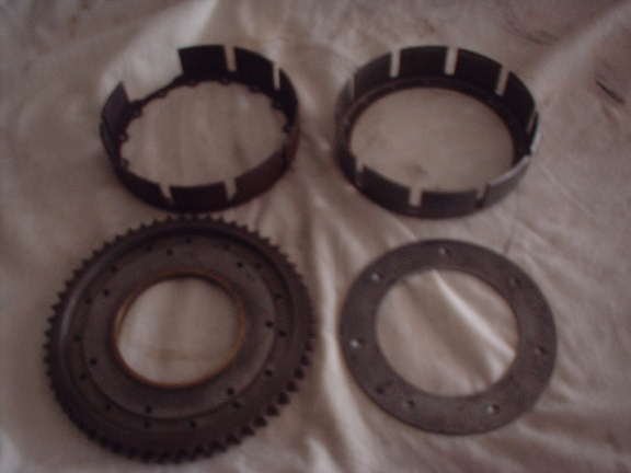
| Clutch Re-Build Info Replacing the Clutch Sprocket Drum The Clutch Sprocket and Drum (Part Number 27535/6) is built up
from 4 major parts and held together with rivets. This design is
not obvious during casual inspection of the The missing part is a flat disk that covers the rivets that hold
the Clutch Sprocket Drum (P/N H81/5) to the sprocket. This plate
fits inside the drum and it is held in place by 8 short pieces of
rod (approximately 0.15” diameter). These rods could be called
“headless In any case, it is possible, with a little patience (and a lot
of hammering) to install a new drum on the old sprocket using only
common hand tools. The first step after removing After the disk has been removed, the 15 rivets that hold the drum
to the sprocket can be removed in a similar manner. The rivets should
be driven from the drum side to avoid having to drill the rivet
heads on the back side.The replacement drum has an inside diameter
that is machined to match a boss on the sprocket.
The boss centers the drum and the drum can be rotated until the
rivet holes line up. Now comes the time consuming part, each rivet
must be inserted from the back side of the sprocket, up through
the drum, and then the rivet must be supported on a suitable Next place the flat disk into the drum and line up the 8 rivet
holes. These holes do not have any countersunk holes to retain the
rivet so it’s easy to cut some small steel rod Bill . |
Torque Values
|
Looking for a Iist of torque values for the Interceptor. Nothing in the
workshop manual...
Does any of your guys have one?
TIA Best regards "Anders" I came up with 20ft. lbs. for the 1a heads & 21 lbs. for the connecting rods . for the newer type 11 the head torque is also 20 lbs. & the rods are 23 lbs. i have a manual for each model as these are the only torque settings given . Good luck "K.Smith" |
Numbers-Engine-Frame
| In regards to the serial # question, the '69 parts book states
the engine # will be found on the driving side of the crankcase below
the cylinder barrel, and the frame # is on the head lug. My engine # starts with 1B and my frame # starts with F and the numbers are both the same after that.It also has a plate riveted on the other side of the neck giving the date and place of manufacture and repeats the frame # on it, stamped into the plate. I took rubbings of both these numbers and sent them to the dating officer in the UK RE club and she was able to tell me my bike had been dispatched to Toronto in Feb 1970, to Firths Motorcycles , a big Brit bike dealer there in those days. Hope this helps someone, "Bob C" |
Clutch and Gearbox Assembly notes
| How do you easily identify the two different springs? One are strong
and one weak. I can not feel any differnce by just compress them by
hand.
How should the inner and outer dished plate be fitted? Inner dish
should be projected outwards the outer inwards. Could anyone explain
this in other All the best
Hope this helps Anders, I've been abroad for the past week, and it doesn't look like you have had an answer to your question, so here goes. 1. Springs. The easiest way to check the springs is to measure the thickness of the wire with a caliper. The weaker springs are wound from thinner wire. The other way is to put pairs of springs between the jaws of your vice, and tighten the vice slowly. The weaker spring will compress more than the heavier one. 2. Clutch plates. The easiest way to remember the correct orientation of the clutch plates is as follows. Note that the raised part of the inner and outer plates must face each other. Thus, the plates are closer together where they are dished. Maybe some ASCII art is in order to illustrate what I'm getting at: Clutch Plates
Hope this helps, .. gREgg |
Gearbox Neutral Finder notes
| Half the time i find i'm not using the neutral lever but i've read
it's not good to sit at traffic lights with the clutch lever in &
in 1st gear .the parts book shows two so called springs in the system
but there doesn't seem to any spring tension on the neutral lever,
could this be the problem ,weak springs ?
Would be happy to hear any tips to correct this ancient original method by r/e to find neural . the bike runs great & shifts well once underway it's the stopping then search for neutral that's a real pain please help (kas 750) Take a look at excellent instructions at http://www.cybersteering.com/cruise/feature/bullet/adj_neutralfinder.html Best regards Anders Lilja |
Enginge Breathing tips
| Here is another one that comes from Captain Norton, but suits our
Interceptors well.. (see our links)
When pistons move up and down they create underpressure resp. overpressure in the crankcase. Overpressure we don't like because it presses the oil out though every hole there is.. and that gives an sweaty engine.. and oil being sucked though the valve guides into the inlet channel. Underpressure we like because it keeps the oil in where it belongs. On the Interceptor there is just a big hole and a flexible hose
to let all those pressures out. To keep the underpressure in you
can put a valve in the hose. Captain Norton advises Motormite Power
Brake Check valve nummer van GM # 18022219 (motormite Help! Products
80190)or Volkswagen.. VW part no. 191 611 933. I went for the Volkwagen
valve and seriously.. no more sweating om my Paulus |
Bonding the cork segments
| Whats the process involved in bonding the cork segments to the
clutch sprocket drum?
I used two-pack epoxy (J-B Weld or equal) to glue cork gasket sheets
to steel clutch disks and the clutch basket. I never had one fail.
The cork gasket did cause some extra clutch drag but the cork never
came off. an automotive supplier who manufactured friction plates for automatic transmissions. These plates look very much like motorcycle clutch plates. They used a fixture machined that was two 'donuts' with a 1/2 inch bolt to clamp them together. I had the prototype shop cut some friction material to fit the basket. I chemically stripped the basket, bead blasted it, then we applied glue and baked it in an oven. Next we used the fixture to clamp the friction material to the basket and then baked that in an oven. The clutch was then assembled into the motor. I believe this bike has not seen much use but it worked fine initially. I know that there are some companies who reline brakes and clutches here in Chicago who can provide the friction material and glue and probably the oven as well. I think there is a guy who makes clutches for Vellocettes and other bikes near Chicago who might be able to perform the same service. Dave Smith is his name and he used to have an ad in Walneck's. Mike might also be interested in doing a small batch of clutch baskets if enough people need it. He would need to source the friction material. I'm sure he still has the fixture. Dimension would be easy to provide, but I think this is pretty simple to work out of you have the basket in front of you. Sorry I can't provide more information on the temperatures and glue material and the thickness of the friction material. If someone is desperate I could make some calls. -RickL |
Failing Oil Seal- crashes engine - MK II only
| Dave, this is the second Series II engine that I've heard of failing
in that manner. The other one that failed was so badly destroyed that
there was not much left to salvage aside from a few studs. Even the
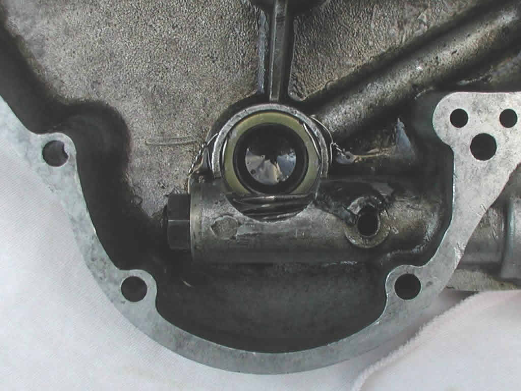
crankcases were smashed. The thing failed because the feed seal in the timing cover came adrift, and was promptly eaten by the pump worm. The loss of oil pressure, and the fact that he was doing an insanely high rate of speed led to an instant destruction. Be sure when you fit a new seal, ... you must NOT use the common garden type lip seal that one gets at a bearing shop: you must use the correct, high pressure type (Norton Commandos have this same weak spot, and though an incorrect seal is prone to failure, their seal is held in place with a circlip so you can see it after it has failed). The Interceptors prior to the Series II have a completely different oil feed system to the crank, which is not susceptible to the problem I described.The Series 1 and 1A have a long quill in the oil feed plug, with a neoprene bung on it ... this slips into the end of the crank. By contrast, the Series II has no oil feed plug, and instead has an oil seal pressed into the timing cover (in the same manner as a Norton Commando engine). The end of the Series II crank has an extension on it that engages with the seal in this oil seal ... as you can see, a completely different system from the older bikes, like the 1965. It is this seal in the timing cover that has a propensity for coming adrift. I too have converted the quill style oil feed plug in my Series 1A to the 'Hitchcock style', and no problems as yet. , .. gREgg NOTE See also Ole's solution with circlip I found the same problem that Gregg had written to you about . He hit it right on the head. The oil seal in the timing cover came undone ,and ended up on the engine side of the crank worm drive for the oil pump. On it"s way over the worm gear, it left part of the seal spring
in the pump worm and some more in the crankcase. The sudden loss
of oil pressure did a job on the left There are 2 cracks in the rod near the big end, so I guess I can
thank God that I shut down when I did. I had recently replaced the
crank seal with one from Hitchcocks, Does anyone know the availability of a high pressure seal as Gregg
mentions? I'll also look into machining a slot for a retaining clip
in the timing cover.(see Ole's link above) Dennis
The seal now can NEVER come loose again, and to replace is easy,
just untwist the wires and repeat. |
Cut the clutch rod in 2-3 places!
| Many years ago Classic & Motorcycle Mechanics magazine published a series of 6 articles about the Enfield/Albion gearbox and clutch. It said that one of the reasons why the clutch doesn't get enough lift is the over-long clutch operating rod which inevitably whips and binds within the gearbox mainshaft. To make the clutch work more effectively they give the suggestion to cut the rod in two or three pieces, squarely refacing the ends, and slipping a suitable diameter ball bearing between the separate pieces. Dont forget to harden the ends by heating till bright cherry red
and dousing in cold water. I followed the suggestion and this surely
helped to make my clutch soft and sweet. Along with buying new surflex
plates, getting the sprocket and drum assembly covered with modern
friction material, shaving some excess weight from the drum etc |