|
Royal Enfield Interceptor - Knowledge Base
The Electrical System
Notes and Modifications
| Unless stated otherwise, the information in this Knowledge Base
is for Royal Enfield Interceptor only. Some information could of course
be applicable to other models. |
Index
Charging System-Alternator Output
Lucas High Output 3 Phase
Ignition Switch Wiring
Ignition Technical Operation, coil, condenser, etc.
Horn
/ Dipper
Converting from positive to negative ground?
Boyer Bransden Ignition with a "negative" ground
Boyer Digital
Interceptor Magnetos
LED light for stop light
Charging System-Alternator Output
|
Does anyone know the peak output of the -67 750 alternator?
I installed an after market halogen headlight .its a 55-60w h4 .
I also installed an ameter in the headlight housing .
The hook is correct ,gauge works fine . The problem is apparently
the alternator does not put out enough to show a charge on the amp
meter .at 2500to 3000 rpms the gauge still shows about 2amps discharge
.
The gauge shows about 10 amp discharge at idle . the battery life
would not be long in this situation. I know my sons headlight wattage
is 40-50w [he has a 71 bsa firebird].
If i modify the socket and change to this bulb might this be enough
of a reduction in current draw to maintain a charged battery and
still have decent brightness of the headlight?
There was a small 4 3/4'' sealed beam on the bike [low brightness]
that is why i changed to new headlight . Any ideas are welcomed
. I understand there is a halogen hs-1 35-35w that is a cross match
of the base on the h-4 but at the loss of britness . Thanks again
for any suggestions . Ken in Penfield , New York
Lucas High Output 3 Phase
I recall that a few months ago, we were discussing the relative
merits of the Lucas 3 phase RM24 vs the older RM19/21 single phase
alternators.
Fortunately, tonight I found a graph from Lucas that puts proof
to the discussion once and for all: it shows that as I'd stated,
the 3 phase alternator produces much more useable power at any engine
speed.
Click pic.to see the Full Graph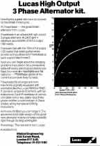
I've pulled off the following key numbers which tell the tale:
Comparison of RM 24 (3 phase) vs RM21 (single phase):
============ ===============
1. Output current at 1500 RPM - 7 amps vs 5.5 amps
2. Power output @ 2400 RPM - 157 watts vs 90 watts
3. Engine speed to produce 120 watts of output (ie Max output of
RM21) - 1800 RPM vs 5000 RPM
4. Maximum alternator output @ required Engine speed
- 180 watts @ 4500 RPM vs 120 watts @ 5000RPM
The important fact is that especially at low engine speeds, the
3 phase system produces much more power, which is the main attribute
of this type of system.
.. gREgg
GREGG !! Absolutely ELECTRIFYING !!!
Can anyone suggest a good supplier of a Lucas RM24. I am in Chicago.
Pardon my ignorance of things British and Lucas, but what do I need?
Do I just ask for an RM24 Alternator?
-Rick
Rick,
You need more than just the RM24 alternator and rotor, but there
are some
options.
You will need the mating 3 phase rectifier, as well as a pair of
matched
Zener diodes for regulation. In place of the special rectifier and
Zeners ,
you could use the 3 phase Boyer Power Box. Alternately, you could
use the 3
phase PODtronics box (which is an adaptation of a Japanese
rectifier/regulator box) that uses SCRs instead of Zeners.
However, before you go making the conversion, are you sure your
RM21 is
really set up correctly? One of our club members (Bruce) was having
charging troubles with his Commando, and I advised him to check
the
following simple details:
1. Ensure his rotor was fully magnetized (he subbed another rotor
which
'felt' like it was more powerful). BTW, this is the most common
problem
with low output, and is easily resolved by replacing with a new
rotor.
2. Ensure the rotor is aligned with the stator. This means ensuring
they
are concentric, as well as the rotor being centered axially with
the
windings when viewed from above. This is the second most common
problem and
easily solved with spacing the rotor and/or stator.
3. If you have one of the older 3-wire *single* phase alternators
and you
are using it in a 12 volt system, two of its wires (green/yellow
&
green/black) must be tied together. Make sure those two are tied
together,
and that they are the correct ones are tied together ... you will
cut the
output if the White-green wire is joined instead. Also, it is imperative
that the windings connected to both windings being joined are functional.
Testing each winding with an ohmmeter for continuity before joining
the
wires is a good start, but even better is each of the windings for
output
with the engine running,
With Bruce's Commando, correcting the above details completely
cured his
charging problems.
.. gREgg
|
Ignition Switch Wiring
I have studied the electrical schematics for the Interceptor. There
is one thing that puzzles me...
How is the ignition switch connected? The switch symbol is a little
unclear for me... something must be missing...
Please help and explain, thanks in advance.
Best regards
"Anders"
Anders,
How old an Interceptor are you talking about here? If it is a 1963
to 1965 vintage machine, it was equipped originally with a magneto,
and hence never had an ignition switch.
Later Inters had coil ignition, and so the switch was placed in series
with the battery as normal.
If you want to replace the magneto, there are several firms that market
replacement electronic ignitions that bolt in place of the mag body.
Depending on the source, they use either a Boyer or a RITA. They may
be worth considering, since I've been seeing more and more magneto
failures during the past 10 years, and they can be costly to put right.
If you want to keep your mag, you may want to think about using a
relay to "disable" your mag while your ignition is off. You can do
this by arranging normally closed relay contacts from ground (earth)
to the cutout contact on your mag. Then, set up an ignition switch,
so that it applies 12 volts to energize the relay coil when the switch
is in the "ON" position .... that will cause the relay contacts to
open, an allow the mag to work.
... "gREgg"
It has been a number
of years since I replced the wiring on my series1a.
FWIW here is what I'd make of your diagram. 
The key switch has two positions. Open or off. On or closed. When
closed it completes the circuit from the battery to the coils. The
back of the key switch has two termianls. One goes to the battery
the other side to the coils. #4 on the lighting switch is live from
the battery and might be connected to the hot side of the key switch
as is the zener. If your key switch will carry the current you can
tie the #4 to the same terminal on the key switch as the coils.
Click for larger picture
That way the key turns off all the power.
HTH
"Rick"
Thanks all for the clearification on the function for the ignition
switch. What confused me was that I thought that the switch was a
three contacts switch with common/normal open/normal close.
MIne Interceptor is in pieces so I can not check this up: Is this
really the case:
1. The lighting is not shut off by the ignition switch.
2. The ignition capacitor is always charged so a bad, leaking capacitor
could empty the battery, more or less short circuiting the battery.
Could the ignition switch stand the current for lightning, 2 coils
and capacitor - I do not think so... perhaps a relay should fix this...
could be hard to cut off the big capacity capacitor with a switch
or relay?
"Anders"
My ignition switch came from J.C. Witney. It carries all of the current
for the ignition and lights. "Rick"
|
Ignition Technical
Operation, Coil, Condenser, etc.
| Coil operation
When the points close, current through the coil primary increases
from zero to a maximum value (determined by circuit resistance)
in an exponential manner, rapidly at first, then slowing as the
current reaches it's maximum value.
The rate at which the current rises is determined by the coil inductance
and the circuit resistance. At low engine speeds, the points are
closed long enough to allow the current to reach a level limited
only by the total
circuit resistance, ie, a DC value.
At higher speeds, the points open before the current has time to
reach this maximum value. In fact, at
very high speeds, the current may not reach a value high enough
to provide sufficient spark, and the engine will begin to miss.
This current through the coil builds a magnetic field around the
coil. When the points open, The current through the coil is disrupted,
and the field collapses. The collapsing field tries to maintain
the current through the coil. Without the capacitor, the voltage
will rise to a very high value at the points, and arcing will occur.
The time for the field to collapse will also increase.
With the capacitor, the current provided by the collapsing field
will discharge through it, limiting the voltage at the points, and
the current/field will collapse very rapidly, having a discharge
path to ground through the capacitor.
The coil, capacitor, and resister form a tuned, oscillator circuit.
When the coil is completely discharged, the capacitor is completely
charged. Now, the capacitor will try to discharge to the coil. Without
resistance, there is nothing to limit the coil or capacitor discharge
current, and the cycle will repeat, ie, the coil will charge, then
discharge to the capacitor, which will charge, then discharge to
the coil, etc.
With the resistance, however, the current is "dampened,"
and the amplitude of the oscillating current is
reduced rapidly, dropping to negligible within 3-4 cycles. When
the magnetic field of the primary coil collapses, it cuts through
the windings of the secondary coil, producing an output voltage.
The magnitude of the output voltage is determined primarily by the
windings ratio and by the speed at which the primary field collapses.
A slow collapse will produce a lower output than a rapid collapse.
Until the arc occurs at the plugs, the output of the secondary is
nearly an open circuit, allowing the voltage to reach a peak before
current is produced.
As soon as the spark occurs, the resistance is reduced, and current
flows through the plug gap, maintaining the arc. The primary and
secondary windings are isolated from each other, so that no current
in one flows through the other.
However, the secondary is connected to the primary at the point
where the primary connects to the points and capacitor, and there
is no direct path for the return of the secondary current other
than through the capacitor. As a result, the capacitor is part of
the secondary as well as the primary. There is an oscillation in
the secondary, just as there is in the primary, for the same reasons.
By properly selecting the coil/capacitor parameters, the designer
can "tune" the circuit to provide the most effective output
voltage, as described below.
Capacitor (Condenser)
The capacitor performs several functions. It prevents the points
from arcing and prevents coil insulation
breakdown by limiting the rate of voltage rise at the points. It's
primary function is to provide for a rapid decay of the primary
coil current. The capacitor also "third-harmonic" tunes
the coil, raising the peak output voltage and increasing the secondary
voltage rise time.
This increases the efficiency and the amount of energy transferred
to the spark plugs. If the coil secondary voltage rises too quickly,
excessive high frequency energy is produced. This energy is then
lost into the air-waves by electro-magnetic radiation from the ignition
wiring instead of going to the spark plugs where we
would like it to go.
Voltage rise time should be more than 10 microseconds; a 50-microsecond
rise time is OK. Conventional systems have a typical rise time of
about 100 microseconds. but mostly, the condenser protects the points.
|
Horn / Dipper
My handlebar is not the original.
So I wonder: How is the Horn/Dipper switch fastened to the original
handle bar?
Screwed in threaded holes in the bar?
Regards
"Anders"
You are correct: Many bikes built around 1967 used a combination switch
that fastened with small screws threaded into holes in the handlebar.
Be aware that there is also supposed to be an insulating pad under
the switch.
.. "Gregg" |
Converting from positive to negative ground?
Does anyone know the proceedure to follow when converting from
positive to negative ground?
Cheer
Rick F
Here I'm assuming that we're talking about a Series 1 or II Interceptor.
Basically, you have to reverse the polarity of every component
that has a
polarity. The simplest way is to replace them with their negative-ground
(earth) counterparts. These would be: the rectifier, and the Zener
diode.
The, you have to reverse the wires going to the blue can capacitor,
and to
the battery.
It is possible to reverse teh connections to the Zener and the
rectifier,
but it is a little trickier if you are not perfectly clear on what
you are
doing: the trick is that the body of the component has to be isolated
from
the frame, and a connection added to it in order to reverse the
connections
to it. In the case of the Zener, it means having to insulate it
from its
heatsink ... there are standard kits available for this in the electronics
world, but its a matter of tracking them down if you don't have
industry
contact.
.. gREgg
|
Boyer Bransden with
a "negative" ground
| Once again I seek the help of the collective. This question
is in two parts. First, does anyone have experience installing the
Boyer Bransden electronic ignition on their Mk1A or Interceptors
in general?
Second, does anyone know if the Boyer Bransden unit can be installed
with a "negative" ground instead of the positive ground
that is prevelant on most British machines? I'm looking into converting
my Mk1A to a negative ground unit. Thanks in advance.
Rick
I use Boyer Bransden on my Series II; it runs fine and was easy
to instal, but has the drawback that when starting, it often will
"kick back" when the kickstarter is swung for the first
time. BB don't seem to have an answer for this.
Nevertheless it is very easy to time, and has proved reliable.
I reckon the engine is a little smoother at high revs, ie comfortable
cruising has gone from 75 to 80 mph.
Your best bet to convert to neg. ground (why?) is to ask BB as they
probably can supply a neg. unit.
Dave Hollyman
I've never tried one on an Interceptor, but I have one on my Bonneville,
and the unit comes with instructions on how to connect it up to
a negative ground machine. I'm not sure it is wise to make the conversion
though. Anyway, familiar with Brit
machines will assume it is positive ground. If the polarity is accidentally
reversed for any reason, it will blow the Boyer, so converting an
Interceptor to negative ground and adding a Boyer may be asking
for trouble unless the owner can be absolutely
certain that he will be the only one to work on the bike.
Bob Cram
I have a Lucas Rita for a Commando on my Series II and had to make
a spacer so the eluctor would clear the points cover (this cured
all my hot starting woes, period) if I had to do it over again I
would look into a Boyer as this might clear the points cover without
the 1/4" spacer.
I also have a Boyer micro digital on my Matchless 650 twin and
wired it up negative ground, Podtronics, 3 phase power base alternator
as per the instructions and it works just fine showing 14.8 volts
across the battery with the lights on.
Mechanics now-a-days are schooled in negative ground machinery
and have to wrap their heads around positive ground so IMHO I would
think that the chances of a mishap are far greater with a positive
ground than with the norm.
Cheers
Rick Fisher
Thanks to you all. The information will be put to good use. The
reason for my query is the desire to install a system that conforms
to most "on the road" bikes today. One of the items I
am installing is an LED tail light unit for both my brakes and tail
lights.
This unit is brighter, (added safety factor), and uses much less
electricity than the
standard double filament bulb leaving more wattage and amps for
my headlight, (hopefully a brighter light than the kerosene lamp
that Lucas installed!). And, since diodes are very particular about
how the positive and negative lines are hooked up, (has to be a
negative ground), the more info I have about a conversion, the better
to make an informed decision before I move to the assembly phase.
As of right now it looks like the entire tail unit will have to
be floated, (ungrounded
or isolated from the frame). The bike will also sport an RM23 alternator,
controlled by a Podtronics regulator, to boost total power availability.
I also came into osession of an older installation sheet from Boyer
Bransden that explains the hook up of it's MkIII unit in a negative
ground environment so that problem is solved. Wiring the
bike will be interesting. If anyone has any tips in this area please
don't
hesitate to post it to the web site.
Once again, thanks to you all. I hope the finished product lives
up to level of help you've all given.
Rick
I've just returned from travel, and note Rick has been having difficulty
in adapting a negative earth replacement LED light to his bike.
Here's some insight ...
Rick,
If you are using the stock Lucas tail light unit, take the red lens
off and have a look inside. You will note that the bulb socket is
actually isolated from earth, because it is held by the molded rubber
base of the light unit. The actual connection from the socket to
earth is made by a thin piece of braid from the bulb socket to the
metal bracket inside the light unit.
So, if you sever that braid, you break the earth connection. Now,
you can connect a separate wire directly to the socket, and not
have to have it go directly to earth. (This achieves the same thing
as floating the subframe, with far fewer complications).
However, I do not think that this is going to help you, since the
brake and tail light circuits are both sourcing current, and the
common lead from the LED tail light has to sink the current to earth.
So, if you have an LED light that's made for negative earth, floating
its common (cathode, or negative) lead in order to go positive earth
will do you no good, since the polarity is still wrong. If you float
this common connection and earth the other leads instead, you cannot
connect the common lead to both the brake and tail light circuits
at the same time and have the functions remain separate .... (hope
this is clear). To do what you need, you must actually reverse the
polarity of how the actual LEDs are connected inside the light.
To reverse the polarity of the LED lights, you will have to sever
the connection tying the two common (cathode) leads together, and
run each to separate wires to act as the connections to the brake
and tail light circuits. The other end of the LEDs - the anode (or
positive) ends - will then need to be tied together to act as the
new earth connection .. bearing in mind that there will be a resistor
in series with each of the LEDs, and those *must* remain in-circuit.
Hope this has helped,
.. gREgg
|
Boyer Digital
| I changed my old Boyer mk 3 to the later digital type of Boyer
electronic ignition. The old one is not very sophisticated as it
advances in a straight line, while the digital one makes a real
curve .
It proved money well spend.. acceleration is better, but more important
the idle is very much improved thanks to a electronic stabiliser.
Because Enfield (like Norton) has a chain driven ignition mounted
on the camshaft the idle is very difficult.. at least it was on
my Interceptor.. But now it is a delight.. going very slow and stable.
But.. an unstable idle can also be the result of an idle jet that
is dirty. On the captain Norton site you'll find advice how to clean
this microscopic little thing which is hidden deep in the inner
parts
of your Concentric.
Paulus
|
Interceptor Magnetos
| Got the '65 Interceptor running today, I set it up with a Lucas
SR2 magneto from a Super Meteor. Spark is very so so, not exactly
fat which made starting hard.
Still, not bad for a 50 year old piece of electrical equipment!
Always liked the SR2 mags but can anyone recommend someone in the
USA where I can get it re-magnetised and new capacitor fitted?
Roger.
The SR2s always give an excellent spark, especially at low speeds,
and its not hard to keep them that way. I'd find it hard to believe
that it needs magnetizing.
Clean and gap the points (standard Lucas fare), and replace the
capacitor. The capacitor is a standard Lucas can type, of the type
you often find in British car applications. You may even find one
at your local Pep Boys store. Its easily accessible inside the housing,
and is about a 10 minute job to replace.
.. Gregg
I don't remember where you are located, but I have had good results
dealing with two people in the US. Mark Seibert did 2 K2F Mags for
me includeing the one on my 65 Interceptor. he does remaging and
he is located here in So Cal. E-mail Address mseibert@adelphia.net.
The other is Bob Kizer
Cypress Ignition Ltd.
Oak Plaza Dr.
Cypress, TX. 77429
281-955-6100
Email PODtronics@aol.com
Hope this helps
Orlan
|
LED light for stop light
| I somehow missed this discussion earlier. Anyway, I just wanted
to bring to
everyone's attention that there's a guy in the U.S. who rides Triumphs,
BSAs
etc. who has developed an LED light that is a straight drop into
the standard
Lucas signal light and, he says, draws only 1 watt instead of 21.
Anyway, he is
now working on a similar replacement for the stop/taillight unit.
His website is:
http://www.freewebs.com/rtetetet1/index2.html
The problem of installing LED tail lights and brake lights on my
MkIA has been solved. The trick is to isolate, (or float as Nathaniel
called it), the tail light assembly and run seperate lines to each
LED and ground hook up.
Since the bike has a positive ground I used the brake light switch
hook up, (two wire), as an isolated switch with one end going to
the LED and the to ground. When the switch is activated to ground
positive flows to the LED.
The Negative is fused through a fuse block and is constant at the
tail light. Since the tail light is isolated, (not grounded), problem
is solved. Actually, only the LED board is isolated. The whole unit
works beautifully.
Rick
|
|